Tank Calibration Services
Advanced 3D laser scanning for accurate tank calibration
Overview
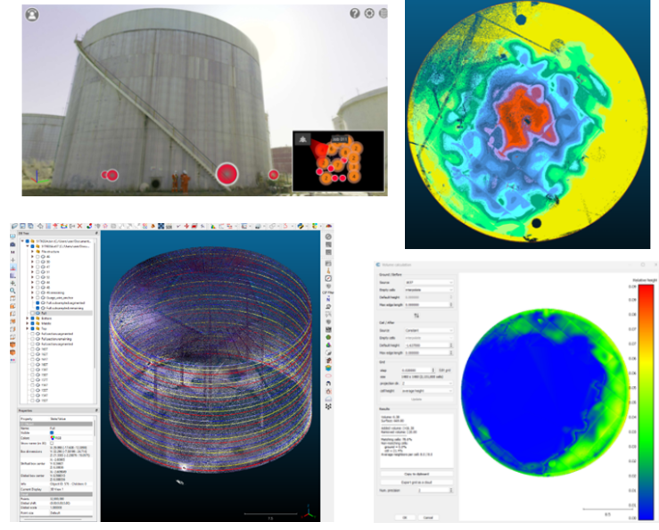
We calibrate upright cylindrical, spherical, rectangular and other tank types used primarily for the storage of petroleum liquids. Our calibration service first addresses procedures for making necessary measurements using 3D laser scanning (High-definition survey) to determine total and incremental tank volumes and then presents the method for the computation of volumes.
Our calibration essentially conforms with API MMPS chapter 2 with the advantage that the Manual Tank Strapping Method is now replaced with 3D laser scanning method (A high-definition form of the electronic optical distance ranging - EODR method - API MMPS chapter 2.2D) which allows for comprehensive high-definition virtual strapping resulting in a safer, more accurate and faster calibration of the tanks.
Advantages of 3D Laser Scanning Over Manual Strapping
i. Higher Accuracy
3D Laser Scanning captures millions of data points (point clouds) to create a precise 3D model of the tank, including irregularities, distortions, and thus delivers measurement accuracy typically within millimeters. Manual strapping relies on fewer physical measurements, which can lead to inaccuracies, especially in large tanks or those with irregular geometries. Manual strapping is also more prone to human error.
ii. Comprehensive Data Collection
3D Laser Scanning enables the measurement of the entire tank's geometry in one survey, including the walls, roof, and floor. This allows for volumetric calculations for any liquid level and the compensation for factors like tilt, deformation, and thermal expansion. Manual Strapping is limited to specific height intervals and does not capture the full tank geometry.
iii. Time Efficiency
3D Laser Scanning is very fast regardless of tank size. Post-processing generates calibration charts and reports efficiently. Manual Strapping is very time-intensive, requiring physical measurement of multiple levels and sections. It takes significantly longer time, especially for large tanks.
iv. Reduced Risk and Safer Operations
3D Laser Scanning is non-intrusive and can be performed externally or inside the tank without requiring personnel to climb or physically interact with the tank. This minimizes exposure to hazardous environments. Manual strapping requires personnel to physically access the tank, often involving climbing, scaffolding, or working at heights with higher risk of injury and exposure to hazardous substances.
v. Ability to Address Complex Tank Geometries
3D Laser Scanning accurately maps complex shapes, including spherical tanks, dome roofs, and tanks with internal structures (e.g., heating coils or nozzles). It accurately captures all irregularities or distortions caused by aging or deformation. Manual Strapping struggles with complex or irregular tank geometries, leading to inaccuracies where they are encountered.
vi. Digital Twin/Record and Future Use
3D Laser Scanning creates a permanent digital record of the tank's geometry. This can be reused for quality audits and future calibrations, inspections, or deformation monitoring without additional surveys. Manual Strapping is limited to paper-based records that are not amenable to quality checks without risky, expensive and time-consuming site re-measurements.
vii. Compatibility with Advanced Analysis
3D Laser Scanning can be readily integrated with software for volumetric analysis, stress analysis, or predictive modelling. It supports adjustments for tilt, thermal expansion, and deadwood with precision. Manual Strapping requires separate calculations for corrections, increasing the likelihood of error.
viii. Cost-Effectiveness Over Time
While initial setup and equipment using 3D laser scanning may be costly, the speed, accuracy, and reusability reduce overall costs in the long term. Manual Strapping may have a lower upfront cost but ultimately have higher operational and overall costs due to time, labor, and repeated surveys, in addition to the risk of associated injury.
TLTFIT Workflow
1. Volumetric Analysis
Volumetric analysis shall be conducted by aligning a 3D model of the tank shell and its appurtenances with the 3D point cloud data. This alignment is achieved by minimizing the overall variance between the model and the point cloud, ensuring an accurate representation of the tank's geometry and features.
2. Tank Status Before 3D Scanning for Calibration Purposes
Before performing 3D laser scanning for tank calibration, the following requirements and conditions must be met to ensure accurate and reliable results:
2.1 General Requirements
Hydrostatic Testing:
- The tank must have been filled at least once at its current location with a liquid of comparable density to the one it is expected to store.
- Typically, a hydrostatic test lasting approximately 24 hours will meet this requirement.
- Prior to the calibration scan, the liquid in the tank must remain undisturbed for at least 24 hours to stabilize the tank's structure and eliminate potential distortions caused by liquid movement.
Tanks with a Nominal Capacity of 80,000 Litres or Less:
- Tanks of this size may be calibrated under any condition of fill, provided they have been filled at least once at their current location.
- Small movements of liquid (e.g., oil) into or out of the tank are permitted during the 3D scanning process without significantly affecting the results.
Tanks with a Nominal Capacity Exceeding 80,000 Litres:
These larger tanks require specific handling based on their construction type:
Bolted Tanks:
- Must have been filled at least once at their current location.
- Should be at least two-thirds full during the calibration process.
- Small liquid movements (e.g., oil transfer) are permissible during strapping but must be monitored to avoid compromising accuracy.
Riveted and/or Welded Tanks:
- Must also have been filled at least once at their current location.
- Can be strapped under any condition of fill, provided the final capacity is computed in accordance with Section 19.6 of API MPMS Chapter 2.2A.
- No liquid movement is allowed during the 3D laser scanning process to ensure precise data acquisition.
3. Descriptive Data
The API Gravity and the temperature of the tank's contents at the time of strapping shall be obtained and recorded. The average API Gravity, average overall ambient temperature at which the tank shall operate, and maximum safe fill height shall be obtained from the tank owner and recorded.
The safe fill height, when required to be indicated in the capacity table, shall be so specified by the owner. The safe fill height in most instances will be less than maximum fill height.
4. Adjusting for Expansion/Contraction and Tilt of Steel Tank Shells
To account for expansion/contraction due to temperature, the correction shell temperature correction guidance provided in API MPMS Chapter 2 section 19.7 shall be applied accordingly. The temperature of the shell shall be determined according to API MPMS Chapter 2 Annex D section D.1.
For tanks containing liquid, correction for circumferences to empty tank basis, shell thickness and fill height liquid stress on internal surfaces shall be computed according to API MPMS Chapter 2 Annex B sections B.1.4, B.1.5 and B.1.6 respectively.
The effect of tilt shall be disregarded for tanks tilted less than 1 part in 70 parts. For tilts equal to or more than 1 in 70, the vertical capacity table shall be adjusted according to API MPMS Chapter 2 section 19.8.
5. Deadwood Management
Where possible, deadwood shall be accurately accounted for, as to size and location, to the nearest 3 mm in order to ensure the following:
- Adequate allowance for the volumes of liquid displaced or admitted by the various parts
- Adequate allocation of the effects at various elevations within the tank
- Precise 3D modelling shall be used to integrate deadwood corrections into the final calibration table
Deadwood shall be scanned, if possible, within the tank. Dimensions shown on the builder's drawings or dimensions furnished by the tank owner will be required and accepted if actual capturing is not feasible.
6. Tank Bottom Assessment
Tank bottoms that are flat, level, and stable under varying liquid loads will have no effect on tank capacity.
Tank bottoms conforming to geometric shapes (e.g. sloping, cone down, crown up, hemispherical, semi ellipsoidal, and spherical segment) have volumes that shall be either computed by virtual incremental filling using point cloud if possible, to scan them. Where not possible to collect non-flat tank bottom data, previous calibration report shall be required and accepted to account for the tank bottom influence on volumetric disparity.
7. Calibration Table Generation
Calibration table shall be generated based on incremental volume. Increments shall be at 1cm and volume shall be in cubic meters (m³).
7.1 Floating Roof Tank Calibration
The calibration of a floating roof tank requires precise 3D scanning of the roof, conducted both from above and below, to ensure all appurtenances are accurately captured. Special attention shall be given to the support legs and the pontoon, enabling comprehensive 3D modelling for deadwood regularization.
The calibration process shall adhere to API MPMS Chapter 2, Section 19.9 guidelines. The critical zone — defined as the area where the roof transitions between floating and resting on its supports — shall have its upper and lower limits clearly marked on the gauge table. A note shall accompany this indication, advising that this range should be avoided for critical volumetric measurements due to potential inaccuracies.
For liquid levels below the critical zone, the tank's capacity will be determined through virtual liquid calibration, which involves detailed 3D modelling of the floating roof. In this process, the floating roof is treated as deadwood, effectively displacing a fixed volume of liquid. For liquid levels above the critical zone, calibration shall involve subtracting a volume equivalent to the floating weight of the roof.
The floating weight includes:
- The roof itself, along with all attached appurtenances that move with the roof.
- Half the weight of the ladder.
- Half the weight of hinged or flexibly supported parts of the drain.
- The full weight of the swing line float.
- Half the weight of the swing pipe.
This weight should be provided by the tank manufacturer/owner and is typically documented in the tank drawings and on the roof nameplate.
It is crucial to note that the accuracy of the calibration outside the critical zone shall remain unaffected by this procedure, ensuring reliable measurement across the tank's operating range.
7.2 Conical and Dome Roof (Fixed Roof) Tanks Calibration
3D scans shall include the roof geometry in scans, particularly where the roof meets the tank shell. Adequate account for the roof deadwood shall be made if the liquid can rise to the roof level (where maximum liquid level is above shells).
7.3 Spherical or Spheroidal Tanks
The difficulties encountered using conventional/traditional strapping techniques are eliminated by the use of the state-of-the-art high-definition survey by 3D laser scanning. All volume correction due to temperature shall be carried out in accordance with API 2552 (D 1408 - 65) Appendix III.
Standards & Compliance
- API MPMS (Manual of Petroleum Measurement Standards) Chapter 2
- API MPMS Chapter 2.2A - Measurement and Calibration of Upright Cylindrical Tanks
- API MPMS Chapter 2.2D - Calibration of Upright Cylindrical Tanks Using the Optical Reference Line Method
- API 2552 (ASTM D 1408-65) - Standard Practice for Calibration of Upright Cylindrical Tanks
- ISO 7507 - Petroleum and liquid petroleum products — Calibration of vertical cylindrical tanks
Deliverables
- Comprehensive calibration report with detailed methodology
- Capacity tables at 1cm increments in cubic meters (m³)
- 3D point cloud data and tank model
- Tank geometry analysis including tilt, deformation, and irregularities
- Deadwood documentation and corrections
- Temperature and stress correction factors
- Digital archive for future reference and comparison
- Certified calibration certificate
Tank Types We Calibrate
- Upright cylindrical tanks (fixed roof)
- Floating roof tanks (internal and external floating roofs)
- Spherical and spheroidal tanks
- Dome roof tanks
- Cone roof tanks
- Rectangular tanks
- Horizontal cylindrical tanks
- Custom or irregular shaped tanks
Why Choose TLTFIT for Tank Calibration?
- Advanced 3D laser scanning technology for millimeter-level accuracy
- Compliance with API MPMS and international standards
- Safer, faster, and more accurate than manual strapping
- Experienced team of calibration specialists
- Comprehensive digital records for future use
- Reduced downtime and operational disruption
- Cost-effective solution with long-term value
- Quality assurance and audit trail